Limit Gauges:-Plug Gauges and its types ,Snap Gauges and its types, Ring Gauge, Radius & Fillet Gauge, Filler Gauge
Limit Gauges:-
→
→if on inspection the dimension of the product produced lies within the permissible limit then the product is accepted.
→but if on inspection the dimension of the product produced does not lie within the permissible limit then the product is rejected.
→In the manufacturing industry the product produced is either of two natures either it will be a shaft or it will be a hole. we have to take the measurement to check its accuracy. but when the production rate is high we cannot choose the method of measurement which is time-consuming
→Therefore to check the manufactured component accuracy within less time We use a special type of inspection device called limit gauges
→limit gauges are non-recording type inspection devices i.e. they do not give the reading of the dimension of the product produced but they only check whether the product produced lies within the permissible limit or not.
Types of Limit Gauges
Plug Gauges:
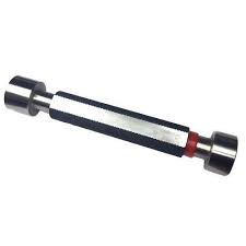
→Plug gauges, also known as pin gauges, are used to measure the hole diameters or depths.
→They consist of a cylindrical or tapered rod with a specific diameter or shape that should fit into the hole being checked.
→ If the gauge can be inserted into the hole up to a certain depth without any resistance, it indicates that the hole is within the acceptable tolerance range.
These are the following types of plug gauges.
1. Single-ended plug gauge:-
In this plug gauge, the gauge Go side and No-Go side are made separately at the end of the gauge.
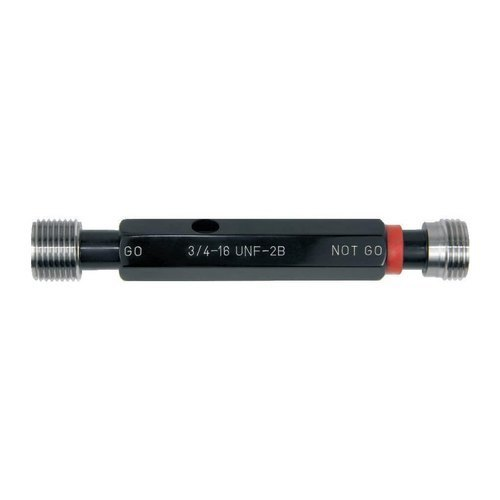
In these plug gauges, both go-side and no-go side are made on two opposite ends of the same gauge.
3. Progressive plug gauge:-
It is a type of limit gauge in which both go
and no other side of gases are made on a single gas and also made
consecutive to each other, both go and no-go sides are separated by
group spacing.
In this type of limit plug gauges at the go side and No-go side Threads are made to check the accuracy of the nut.
Snap Gauges:
→
→They consist of two jaws or anvils that can be adjusted to a
specific width.
→The workpiece is inserted between the jaws, and if it fits within the specified width without any play or excessive tightness, it is deemed acceptable.
Types of snap gauge:-
1. Fixed single-ended snap gauge:-
In this Go side which corresponds upper limit of the shaft and the No Go side which corresponds to the lower limit of the shaft are made separately.
2. Double-ended fixed snap gauge:-
A double-ended fixed snap gauge is a type of limit gauge used to measure the outside diameter of a cylindrical workpiece.
→ It consists of two opposing anvils or jaws that are fixed in position and cannot be adjusted. The snap gauge is designed to provide a quick and accurate measurement of the workpiece's diameter by simply placing the workpiece between the anvils.
3. Adjustable snap gauge:-
An adjustable snap gauge is another type of limit gauge used to measure the outside diameter of cylindrical workpieces. Unlike the double-ended fixed snap gauge, the adjustable snap gauge allows for fine-tuning and adjustment of the anvils to accommodate different diameter sizes within a specified range.
Ring Gauge:-
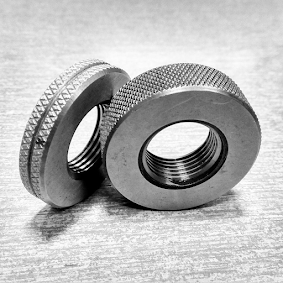
Ring gauges are used to measure the outside diameter or thickness of cylindrical objects such as shafts or sleeves.
→ They are circular in shape and have a precisely machined bore with a predetermined diameter.
1. Construction: A radius and fillet gauge typically consist of a set of curved blades or pins of various radii. These blades are mounted on a handle or a frame, which allows for easy handling and measurement.
2. Blade Selection: The gauge set includes a range of blades with different radii or fillet sizes. Each blade is marked with its corresponding radius or fillet dimension.
3. Measurement: To use the radius and fillet gauge, the appropriate blade is selected based on the desired radius or fillet size. The blade is then placed against the curved surface or edge being measured.
4. Fit and Comparison: The blade is carefully aligned with the curved feature, ensuring that it makes contact along the entire length of the radius or fillet. The operator evaluates the fit by comparing the curvature of the feature with the curvature of the blade. The blade that closely matches the contour of the feature is the one that represents the correct radius or fillet size.
5. Reading and Documentation: Once the best matching blade is identified, the operator can read the radius or fillet size directly from the marked measurement on the blade. This measurement can be recorded for documentation or further analysis.
6. Calibration and Maintenance: It is important to periodically calibrate the radius and fillet gauge set to ensure its accuracy. The blades should be kept clean and free from debris or damage. Care should be taken to handle the blades carefully to avoid any distortion or wear.
Filler Gauge:-
A feeler gauge is a thin strip or set of strips used to measure the gap or clearance between two surfaces. It is typically composed of a series of metal blades of various thicknesses, often bound together as a single tool. Feeler gauges are commonly used in automotive, engineering, and other mechanical applications for tasks such as setting valve clearances, checking gaps in spark plugs, and measuring tolerances.
2. Blade Selection: To measure a gap or clearance, the appropriate blade from the feeler gauge set is selected. The blade should be smaller in thickness than the gap being measured but larger than any gap that does not exist.
3. Measurement: The selected blade is inserted into the gap, and the operator gently slides it back and forth. The aim is to find the blade that fits snugly into the gap without excessive force or looseness.


Comments